SALLEN-KEY 2-CH BANDPASS FILTER MODULE FOR AMPLIFIER BUILDERS
INTRODUCTION
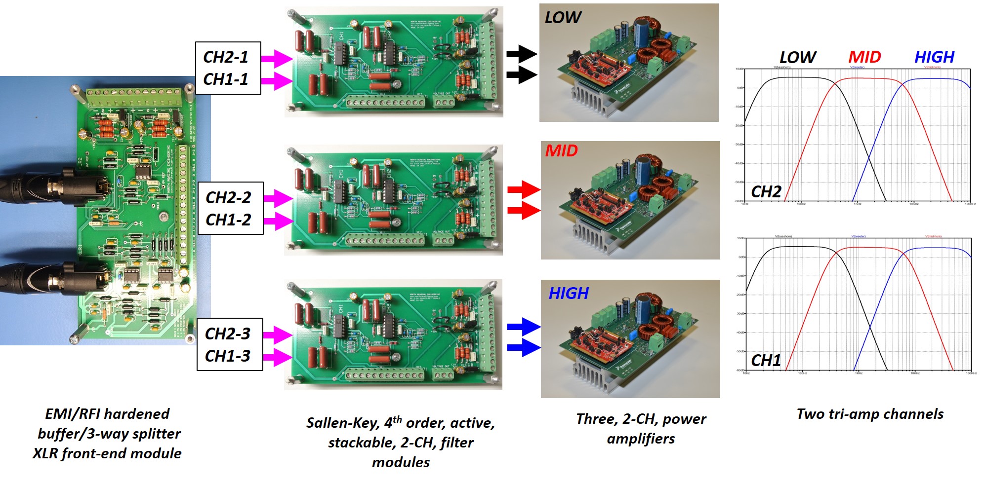
Described here is a 2-channel active filter module that can be used to build active subwoofers, bi-amp or tri-amplified loudspeaker systems. The module is easily configured to apply a 4th order (24dB/oct) bandpass filter to each driver in the system. By changing capacitor and resistor pairs, the -3dB corner frequencies of the passband are selected to suit the acoustic requirements of the drivers. The module accepts two small signal inputs from a typical source, applies filtering to each input and outputs the signals to a two channel amplifier.
Two modules are required for bi-amplified systems. In a tri-amplified setup, three modules are used to provide filtered outputs to an amplifier dedicated to the low, mid and high frequency drivers. North Reading Engineering has developed an amplifier front-end that handles the task of splitting input signals to enable either bi-amp or tri-amp type of arrangements. Amplifier builders can also integrate the filter module into the front end of their own design.
TECHNICAL DESCRIPTION
The filter module can provide any two channel audio amplifier with quiet, bandpass filtered signals. Power supply voltage, small signal input and filtered output connections are made using Phoenix Contact screw clamp, terminal blocks. Boards are fabricated in the USA. Pb-free, RoHS compliant assemblies are also available. The board can be powered from any center-tap power supply capable of providing between +/-24 to +/-100VDC.
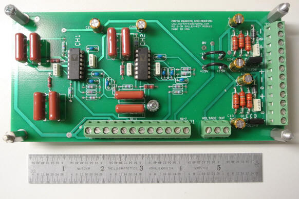
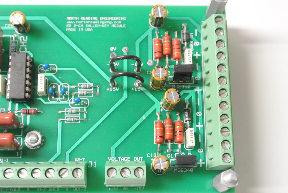
Op-amp packages are installed in Mill-Max sockets which allows for replacement of damaged devices or substitutions. The AD713 BiFET quad operational amplifier has been selected as the default device. Below are photos of the module. Photo left shows component layout. Three terminal blocks are used to make connections. J1 is a 12 position (horizontal) terminal block used for input and output signals, J2 is a 12 position (vertical) terminal block for power connections to the board and power distribution to additional modules. The 3 position terminal block adjacent to J1 provides access to the on-board +/-15VDC op-amp power supply. For amplifier designs where +/-15VDC power is available (say from the main power supply circuit), the on-board supply can be disconnected entire from the filter by removing the two black jumper wires shown in the right photo (the on-board power supply circuit is located to the right of the jumpers). The power supply resistors are rated for 2W.
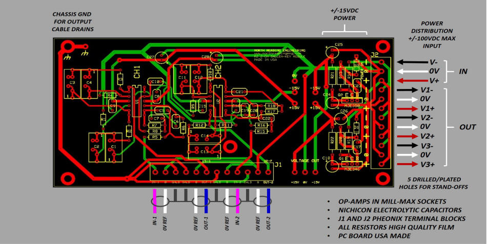
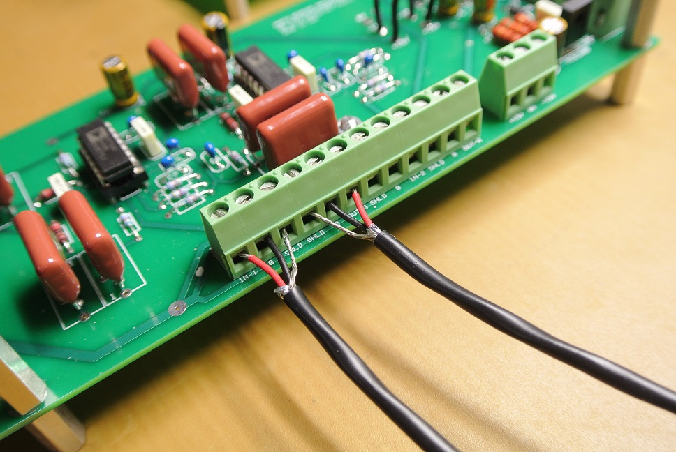
Connections to the module are shown in the figure below. External power supply voltage is provided at the POWER IN connections of J2. To facilitate the distribution of power to other small signal circuits, J2 provides voltage taps for three additional circuits (total current drawn not to exceed 3A). J1 shows two signal inputs (fuchsia) and two corresponding filtered outputs (blue) connections. The filters for each channel are independent and can assume any bandpass topology the builders requires.
Typical small signal outputs made at J1 are shown below left using two-lead, shielded wire (Alpha Wire, 2461C). Each output consists of three leads, the signal lead (RED), 0V power supply reference (BLK) and shield drain (bare). Phoenix terminal blocks very reliable. The screw clamp connections do not loosen from vibration or repeated use. In an actual build, the exposed leads shown would be enclosed in shrink tubing.
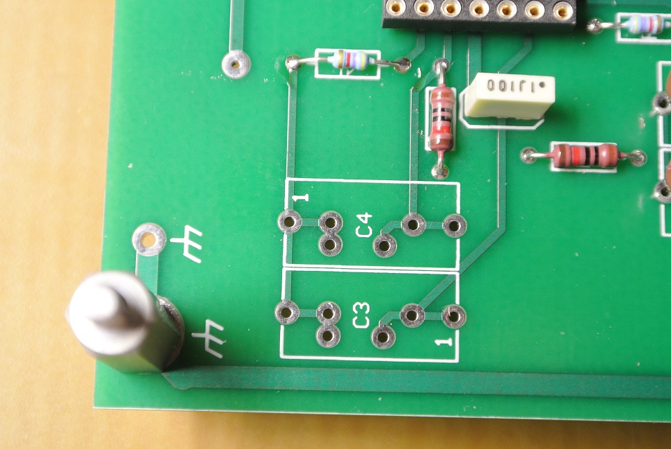
Below right shows typical solder pad location for the high pass, -3dB corner frequency capacitors (C1-4 and C12-14). The configuration provides board real estate for polyester capacitors with 5.0, 7.5 and 15mm lead wire spacing thus enabling a wide range of capacitor sizes and associated -3dB corner frequencies. Small signal shield drains trace back to a common location identified as chassis ground. Note chassis ground is enabled by a either metal standoff to a metal chassis or, if insulated standoffs or the chassis is non-conductive, a soldered lead wire connection back to a common ground reference is provided.
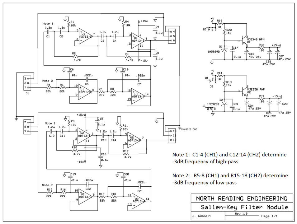
The schematic for the design is shown below. U1 and U2 are AD713 14-Lead PDIP op-amp packages. The on-board -/+15VDC power supply is also shown, right.
BASSHORN FILTER
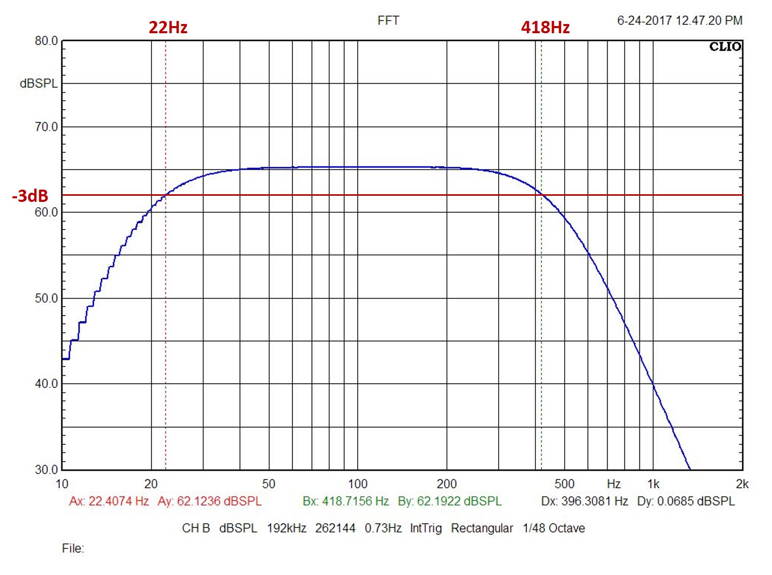
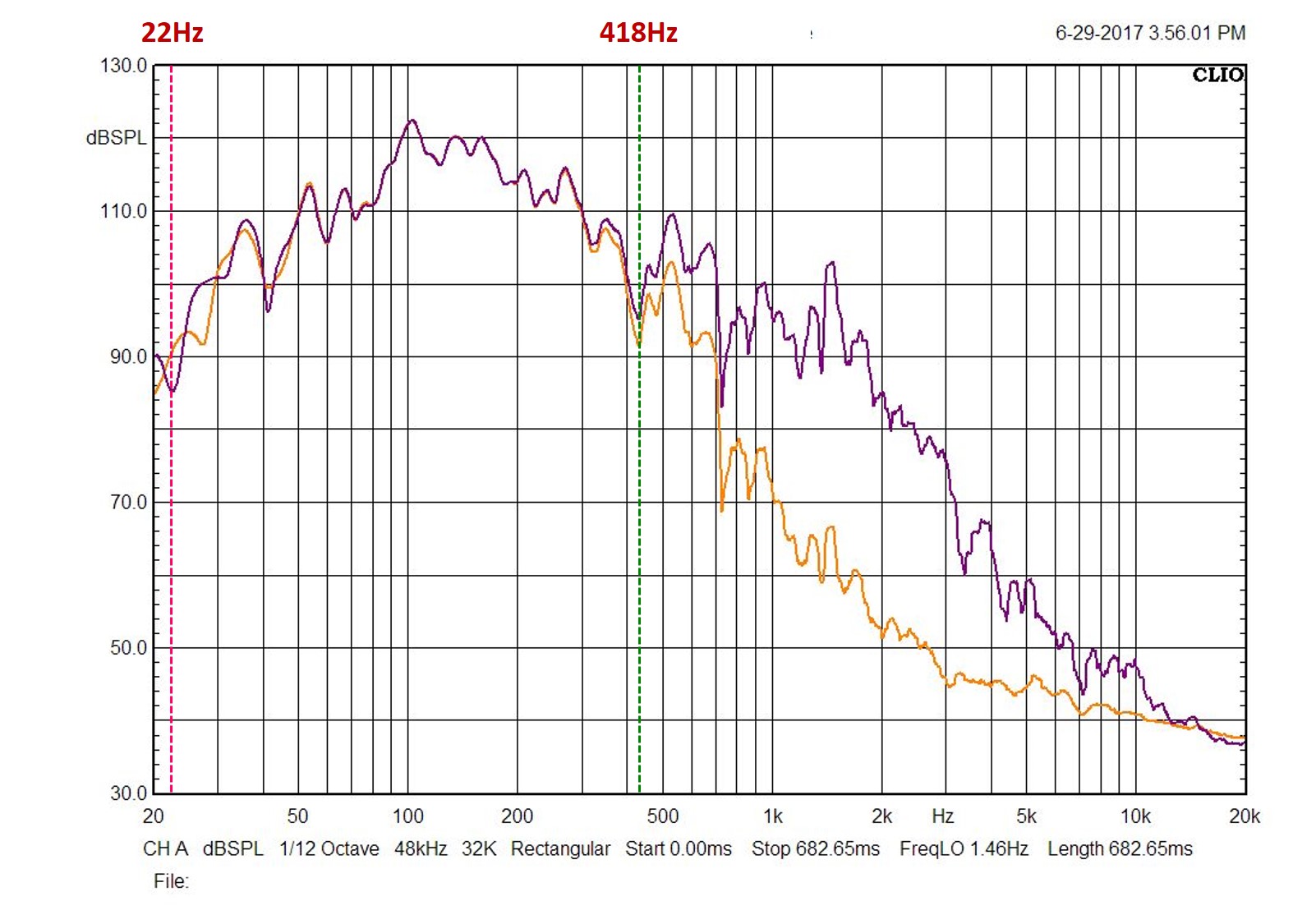
The module can be used to apply active filtering to a bass horn. For example, consider the Klipschorn folded bass horn. A filter was configured to provide a -3dB low pass at 418Hz whilst the high pass was selected to limit very low frequency signals provided by the amplifier from energizing the woofer. Very low frequency (<30Hz) signals are well below the range were the bass horn radiation resistance is significant. Amplifier signals in the very low frequency range cause the woofer to make large excursions that are not horn loaded. This leads to distortion. The low frequency filtering approach also provides the necessary filtering to add a subwoofer.
The filter output signal sent to amplifier, shown in the plot lower left, is obtained by setting C1-4 = 1.2uF and R5-8 = 23kOhm (see CH1 schematic above). The actual acoustic response of the Klipschorn bass horn driven by the amplifier is shown in the plot, right. The purple response is without the filter and the gold response is with the filter active. As evident in the acoustic response, the passband (between 22 and 418Hz) shows the typical "peaky" response of the factory bass horn and is unaltered by the filter. In the stopbands however, the filter provides attenuation which, based on the amplifier FFT response, is -24dB/oct (4th order).
CORNER FREQUENCY SELECTION
The -3dB corner frequencies of the passband can be determined analytically using LTSPICE. Builders proficient with LTSPICE will be able to simulate the response of the filter and derive C and R values for both channels to suit their application (LTSPICE models that simulate the module response using the AD713 package will be provided). North Reading Engineering will also determine component values for customers that either know the crossover frequencies for their applications or require assistance to determine them.
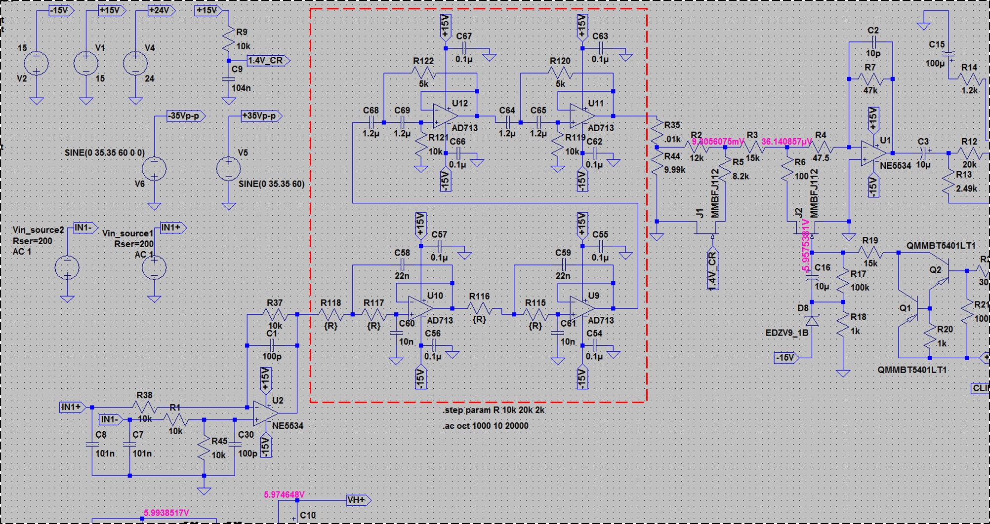
An example of integrating the filter module into an amplifier design, using the LTSPICE simulator, is shown below. The input to the module is an NE5534 balanced to unbalanced buffer and the module output signal goes to a potentiometer which provides volume adjustment of the amplified passband signal.
SUMMARY
If you have interest in either purchasing or building the Sallen-Key filter module please contact North Reading Engineering. If you have an application in mind and would like to discuss if the module will work in that application, just send an email (below) and I'll be glad to discuss the application with you.
PRICING
1. R2.0 Sallen-Key Filter Module, Aluminum standoffs, complete with -3dB corner frequencies set to customer requirements, FFT performance data:
email for pricing, quantity discounts are available
2. R2.0 Sallen-Key filter module PC Board (made in USA), parts list: $49
This webpage and its contents are the property of John Warren of North Reading Engineering, North Reading, MA 01864 USA. No part of the above work may be copied and published, in part or in total, without written permission.
© 2018 John Warren